

由于前面买的核心板,供电老有问题,使得我现在的项目又改用了以前用的F103ZET6微控制器!
1、实验目的
1)产生脉宽任意可调的单脉冲(在允许的范围内)
2、硬件:通用定时器3、通用定时器4
3、单脉冲模式介绍
单脉冲模式允许计数器响应一个激励,并在一个程序可控的延时之后,产生一个脉宽可程序控制的脉冲。
可以通过从模式控制器启动计数器,在输出比较模式或者PWM模式下产生波形。设置TIMx_CR1 寄存器中的OPM 位将选择单脉冲模式,这样可以让计数器自动的产生下一个更新
事情UEV时停止。
仅当比较值与计数器的初始值不同时,才能产生一个脉冲。启动之前(当定时器正在等待触发),必须配置如下:
向上计数方式:CNT (计数器寄存器) < CCRx (比较寄存器)< ARR(自动装载寄存器)
向下计数方式:CNT > CCRx。
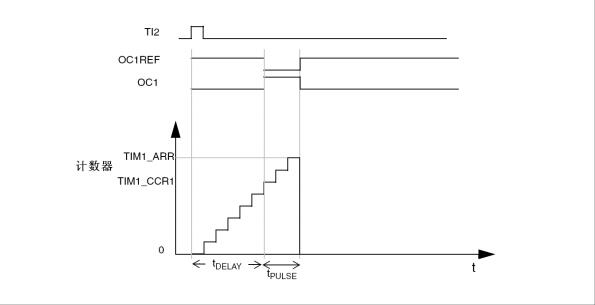
需要在从TI2输入脚上检测到一个上升沿开始,延迟tDELAY 之后,在OC1上产生一个长度为tPULSE 的正脉冲。
具体的可以看参考手册。
4、软件设计
/**
******************************************************************************
*@filetimonepulse.c
*@authorCawen
*@versionV1.0
*@date2015-12-22
******************************************************************************
*/
/*Includes------------------------------------------------------------------*/
#include"timonepulse.h"
/*Privatevariables---------------------------------------------------------*/
uint16_tPrescalerValue=0;
/*
*FunctionName:GPIO_Configuration
*Description:ConfiguretheGPIODPins.
*Input:None
*Output:None
*Return:None
*Attention:None
*/
voidGPIO_Configuration(void)
{
GPIO_InitTypeDefGPIO_InitStructure;
/*TIM4_CH1pin(PB.06)configuration*/
GPIO_InitStructure.GPIO_Pin=GPIO_Pin_6;
GPIO_InitStructure.GPIO_Mode=GPIO_Mode_AF_PP;
GPIO_InitStructure.GPIO_Speed=GPIO_Speed_50MHz;
GPIO_Init(GPIOB,&GPIO_InitStructure);
/*TIM4_CH2pin(PB.07)configuration*/
GPIO_InitStructure.GPIO_Pin=GPIO_Pin_7;
GPIO_InitStructure.GPIO_Mode=GPIO_Mode_IN_FLOATING;
GPIO_Init(GPIOB,&GPIO_InitStructure);
}
/*
*FunctionName:TIM4_Configuration
*Description:TIM4configuration:OnePulsemode
TheexternalsignalisconnectedtoTIM4_CH2pin(PB.07),
TheRisingedgeisusedasactiveedge,
TheOnePulsesignalisoutputonTIM4_CH1pin(PB.06)
TheTIM_Pulsedefinesthedelayvalue
The(TIM_Period-TIM_Pulse)definestheOnePulsevalue.
TIM2CLK=SystemCoreClock,wewanttogetTIM2counterclockat24MHz:
-Prescaler=(TIM2CLK/TIM2counterclock)-1
TheAutoreloadvalueis65535(TIM4->ARR),sothemaximumfrequencyvalue
totriggertheTIM4inputis24000000/65535=300Hz.
TheTIM_Pulsedefinesthedelayvalue,thedelayvalueisfixed
to682.6us:
delay=CCR1/TIM4counterclock=682.6us.
The(TIM_Period-TIM_Pulse)definestheOnePulsevalue,
thepulsevalueisfixedto2.048ms:
OnePulsevalue=(TIM_Period-TIM_Pulse)/TIM4counterclock=2.048ms.
*Input:None
*Output:None
*Return:None
*Attention:None
*/
voidTIM4_Configuration(void)
{
TIM_TimeBaseInitTypeDefTIM_TimeBaseStructure;
TIM_ICInitTypeDefTIM_ICInitStructure;
TIM_OCInitTypeDefTIM_OCInitStructure;
/*TIM4andGPIOBclockenable*/
RCC_APB1PeriphClockCmd(RCC_APB1Periph_TIM4,ENABLE);
RCC_APB2PeriphClockCmd(RCC_APB2Periph_GPIOB,ENABLE);
/*Computetheprescalervalue*/
PrescalerValue=(uint16_t)(72000000/10000)-1;
/* Time base configuration */